Physical Layer
 View on GitHub
Elements
- The most basic form of communication is between a transmitter and a receiver. Here are some elements in the communication:
- Source, DTE
- Transmitter, DCE
- Transmission, Medium
- Receiver, DCE
- Destination, DTE
- DTE is Data Terminating Equipment(DTE) and DCE is Data Circuit Terminating Equipment
Continuous signal vs discrete signal
Continuous signal (e.g. speech) which contains various levels of amplitude, also known as a analog signal.
Discrete signal (e.g. binary) contains only specific levels of amplitude, also known as a digital signal.
Periodic signal
A signal is periodic if an only if . Basically if a signal repeats over a fixed period then it is periodic
Example: sine wave,
where is amplitude, is frequency and is phase.
You can use constructive and destructive interference between signals to find different frequency.
Fourier Series
You can use the following formula to reconstruct a signal between a certain time .
Spectrum of signal
- Spectrum of a signal is the range of frequencies where it has energy/power content
- Absolute Bandwidth is the width of its spectrum
- Band-limited Signal is a signal with finite absolute bandwidth
- All band-limited signals expand from negative infinity to positive infinity.
- Effective Bandwidth is the area of a spectrum where most of the signal is contained
Channel capacity
Nyquist formula
where
- W = bandwidth in hertz
- M = number of discrete signal levels
- C = theoretical maximum capacity in bits per second
Signal Impairments
As a signal propagates along a transmission path there is loss, attenuation of signal strength. The solution to this is to compensate the attenuation, we can use devices inserted at various points to "boost" signal's strength (amplifiers).
Impact:
- degrade the signal quality for analog signals
- introduce errors in digital signals (i.e. 0 may be changed to 1 and vice-versa)
Types:
- signal attenuation
- delay distortion
- noise
Attenuation
- The amplitude of signal decreases with distance over transmission medium. Repeaters and amplifiers are used to restore the signal to its original level
- Attenuation is an increasing function of frequency
- measured in Decibels (dB)
Decibel
- Gains and losses are expressed in decibels (dB)
where:
- = number of decibels
- = power at destination
- = power at source
- = logarithm base 10
The decibel is a measure of relative, not absolute difference. For example a loss from 1000 W to 500 W is a loss of 3 dB. Similarly a loss from 10 mW to 5 mW is also a loss of 3 db. A loss of 3 db halves the strength where as a gain of 3 db doubles the strength.
Decibels are useful to determine overall gain or loss in a system. This can be done through addition and subtraction.
Amplifiers and Repeaters
Amplify the received signals (this includes useful signal plus noise). Repeaters recover the digital information and retransmit it.
Amplifiers can be used with analog and digital communication systems.
Repeaters can be used with digital communication systems. They make decisions on received signals and decide how to transmit the original signal. Sort of like broken telephone (but these are more accurate).
Noise
Thermal noise
This is a type of noise that is always presents because of the thermal agitation in electrons in a conductor.
The amount of thermal noise power in a BW of 1 Hz is given by: , where
- noise power density
- Boltzmann Constant
- temperature in Kelvin
Intermodulation noise
Occurs when different frequencies are passed through the same non-linear device.
Effect: produces signals at multiples/sums or difference of frequencies of the original signal.
Crosstalk
Unwanted coupling between signal paths. Example: more than one conversation heard.
Impulsive noise
Non-continuous noise consisting of irregular pulses or noise spikes of short duration and of relatively high amplitude. This can be caused by external electromagnetic disturbances and faults in the communication system.
Delay distortion
The speed of propagation of a sinusoidal signal along a transmission line varies with the frequency. For a signal with multiple frequencies, the arrival at the receiver is different.
The effect of delay distortion tends to increase with the size of the signal bandwidth (=> it increases with an increase in transmission rate). The pulses become distorted, spread in time and can spill over to neighboring pulses, make their detection difficult. Inter-symbol Interference is the incorrect interpretation of the received signal.
Atmospheric absorption
Strength of signal falls off because the atmosphere absorbs some of its energy.
Attenuation and delay are greater at higher frequencies, causing distortion.
Inter-symbol Interference
Inter-symbol interference (ISI) occurs when a pulse spreads out in such a way that it interferes with adjacent at the sample instant.
Example: assume polar NRZ line code. The channel outputs are shown as "smeared" (width becomes ) pulses (spreading due to bandlimited channel). Basically the signal doesn't seem that accurate.
Causes of Impairments
- Reflection, occurs when signal encounters a surface that is large relative to the wavelength of the signal
- Diffraction, occurs at the edge of an impenetrable body that is large compared to wavelength of radio wave
- Scattering, occurs when incoming signal hits an object whose size in the order of the wavelength of the signal or less
Multipath propagation
- Obstacles reflect signals so that multiples copies of a signal may arrive at the receiver at different and therefore with different phases
- If phases add destructively the signal level declines and vice versa
- even movement of short distances (in the order of ) the signal can vary greatly
- also produces ISI
Solution: Equalizers
Devices that take the original signal and they themselves distort it, and try to correct the signal to the original signal.
Adaptive Equalization
- Used to compensate the distortion introduced by the channel
- Tries to reverse the unequal response of the channel, both in amplitude and phase, to the frequency components of the transmitted signal
- commonly adaptive in the sense that the channel response is periodically estimated and the equalizer adapts accordingly
- useful to combat ISI
- involves sophisticated digital signal processing algorithms
Channel capacity without noise
Nyquist formula
where
- = bandwidth in hertz
- = number of discrete signal levels
- = capacity in bits per second
Channel capacity with noise
Shannon-Hartley formula
where
- = bandwidth in hertz
- = signal-to-noise ratio
- = max theoretical capacity in bits/second
Digital vs. Analog Transmission
- Digital technology
- VLSI product became "low cost"
- Data integrity
- Ex. the use of repeaters guarantees the integrity of the data being transmitted
- Capacity utilization
- links can be shared (multiplexed effectively)
- Security and privacy
- encryption techniques can be applied easily to digital data
Bit rate and baud rate
- Bit rate: number of bits transmitted per second
- Baud rate: number of signal changes per second
Relation:
bit rate = baud rate
where number of bits per change
Transmission media
Guided transmission media
- Twisted pair
- coaxial cable
- optical fiber
Wireless transmission
- microwave
- radio
- infrared and millimeter waves
- light-wave transmission
Twister pair
- widely used in telephone network
- used for either analog or digital transmission
- attenuation very strong with frequency
- analog: amplifiers every 5-6 km
- digital: repeater every 2-3 km
- low noise immunity
- crosstalk is a problem
- poor channel characteristics
- easy to install, repair
- low cost
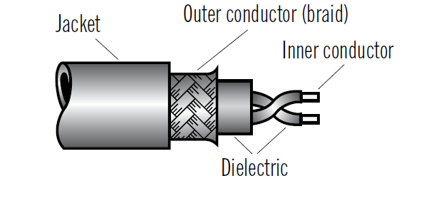
Coaxial cable
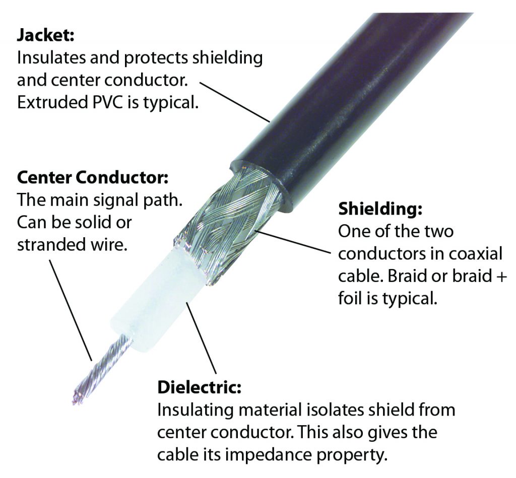
- Baseband commonly used for digital transmission
- one channel
- Broadband commonly used for analog
- multiple channels
- two types
- dual cable system
- single cable system
- attenuation linear with frequency
- better noise immunity
- error rate:
- baseband:
- broadband:
- 1 km baseband cable = up to 2 Gbps
- 100 km broadband cable = 300-450 MHz
- Moderate cost
Optical fiber
- thin (2 to 125 m), flexible medium capable of conducting an optical ray
- three concentric: the core, the cladding and the jacket
- idea: refraction principle
- utilization: light trapped by total internal reflection when...
Three components:
- light source (LED or laser diode)
- transmission medium (fiber)
- detector (photodiode)
Two major types of fiber:
multi-mode fiber (largely used)
single mode fiber (expensive but can be used for long distances)
attenuation very low
high noise immunity
error rate:
100 km = ~2 Gbps
Unfamiliar technology: high skills required
Lightweight and expensive
Wavelength Division Multiplexing (WDM)
- send more than one wavelengths through the same fiber
- allows re-use of fiber
Radio Transmission
- Radio waves
- easy to generate, can travel long distances, penetrate buildings at lower part of spectrum, omnidirectional (all directions from the source)
- widely used for indoor and outdoor communication
- Low noise immunity
- interference from electrical equipment
- multipath interference
- co/adjacent-channel interference
- Attenuation increases with distance "fast"
Wireless Transmission patterns
- directional
- the transmitting antenna puts out a focused electromagnetic beam
- omnidirectional
- transmitted signal spreads out in all directions
Microwave Transmission
- Widely used
- directional
- repeaters are needed
- Higher signal to noise ratio
- They do not penetrate through buildings
- Multipath fading can occur
Terrestrial Microwave
- parabolic dish
- 10 feet in diameter
- line-of-sight transmission
- max distance between 2 antennas $d =3.57(\sqrt{Kh_1}+\sqrt{Kh_2}) where
- = height of antenna one
- = heigh of antenna two
- (adjustment factor)
Applications:
- long-haul communications
- TV and voice communications
- transmission in small regions
Characteristics:
- attenuation is the major source of loss
- is distance, is wavelength, expressed in the same units
- loss varies as the square of the distance
Satellite Microwave
A satellite is a microwave relay station used to link 2 or more ground-based microwave transmitters/receivers.
A single orbiting satellite will operate on a number of frequency bands, called transponder channels.
Satellites are Geostationary (stays in position over the earth).
Applications:
- television distribution
- long-distance telephone
- private business networks
Transmission characteristics:
- 4 GHz / 6 GHz, 12 GHz / 14 GHz, 15 GHz / 17 GHz
- below 1 GHz there is significant noise from natural sources, including galactic solar and atmospheric noise
- 20 GHz to 30 GHz
- Personal Satellite Communication systems
- High-Definition TV (around 23 GHz)
Infrared, Optical and millimeter waves
- Used for short-range communication
- relatively directional
- don pass-through solid object
- mmWave and Visual Optical proposed for 5G networks
Free Space Lightwave Transmission
An application that connects two LANs in two buildings via lasers
- high bandwidth, very low cost and easy to install
- laser cannot penetrate rain or thick following
- work well on sunny days
Digital Data/Digital signals
- Modulation rate: rate at which signal level is changed
- Digital signaling rate/data rate: signal rate (bits/sec) that data is transmitted
- Duration of length of a bit is the amount of time it takes for the transmitter to emit a bit. The bit duration,, for a data rate, is
Data Rate vs. Modulation Rate
- data rate
Digital Data/Digital signals
- Unipolar signal: same algebraic sign
- Bipolar signaling: one logic state is represented by a positive voltage level, and the other by a negative voltage level
Encoding Schemes
Five evaluation factors:
- Signal spectrum
- lack of high-frequency components means that less bandwidth is required for transmission
- Clocking
- every bit being received needs to be identified
- Error detection
- useful to be able to detect errors at the physical level
- Signal interference and noise immunity
- Cost and complexity
3 main techniques:
- Nonreturn to Zero (NRZ)
- maintains a constant value for the duration of a bit time
- the data is encoded as the presence or absence of a signal transition at the beginning of the bit time.
- this type is called differential encoding (the signal is decoded by comparing the polarity of adjacent signal elements)
- Advantage: make efficient use of bandwidth
- Disadvantage: presence of a dc component and lack of synchronization
- Multilevel Binary
- uses more than 2 signal levels, bipolar AMI (binary 1 pulses alternate in polarity, pseudo-ternary (the binary 0 pulses alternate in polarity)
- Advantages: no net DC components, pulse alternation provides error detection
- Disadvantage: loss of synchronization, long string of 0/1 occurs for bipolar AMI/pseudo-ternary
- Biphase
- there is a transition at the middle of each bit period
- Advantages: synchronization, error detection, no DC component
- Disadvantage: higher modulate rate than NRZ, higher BW
Evaluation
- NRZ
- lack of synchronization capability; widely used for digital magnetic recording but not for signal transmission
- Multilevel binary
- long string of 0s (Bipolar‐AMI) and 1s (pseudo-ternary) cause synchronization problems (scrambling techniques are used to address this deficiency);
- it is easy to detect isolated errors; it is not as efficient as NRZ (three signal levels are used instead of 2 levels used in NRZ)
- Biphase
- no synchronization problems; good error detection; more bandwidth is needed (as many as two transitions per bit time)
Data Encoding
Encoding is done using modulation onto an analog signal.
Modulation techniques
- Amplitude modulation
,
- where the term is the carrier and is the input signal, is the modulation index (ratio of the amplitude to to the carrier).
- simplest form of modulation
- Angle modulation
- phase modulation: where is the phase modulation index
- frequency modulation: where is the frequency modulation index
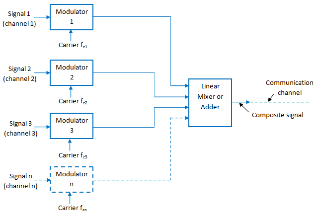
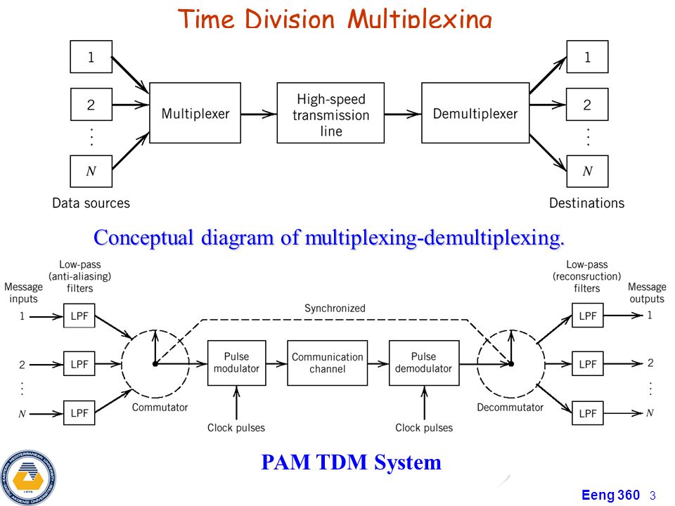
Multiplexing
- Objective: share a link between several users
- Two basic techniques: FDM (Frequency Division Multiplexing) and TDM (Time Division Multiplexing)
Frequency Division Multiplexing
Problems:
- Crosstalk
- guard bands should be carefully chosen
- a voice signal has an effective bandwidth of 3.1 kHz; a channel of 4kHz is adequate to avoid cross talk
- Intermodulation noise
- nonlinear effects of amplifiers on a signal in one channel can produce undesirable frequency components in other channels
- More challenging and expensive RF technology (narrow filters; large)
- Inefficiency
- channels might be allocated to sources that are not using them all the time
Nonlinear Effects in FDM
- Received signal is sum of multiple carriers
- Receiver power amplifiers are operated nonlinearly (near saturation) for maximum efficiency
- The nonlinearities cause intermodulation (IM) frequencies to appear in the amplifier output
- IM components can interfere with other channels in the FDMA system
Time Division Multiple Access
- TDMA systems divide the radio spectrum into time slots.
- Only one user can transmit or receive during a one time slots
- Usually, each user may occupy the channel once during a time frame, where one frame comprises time slots
- TDMA systems transmit data in a buffer and burst method.
- The transmission is non‐continuous.
- Unlike FDMA systems which can transmit analog signals, TDMA must transmit data and digital modulation must be used
Featured:
- Only one carrier, no Intermodulation
- Number of time slots per frame depends on bandwidth, desired date rate, modulation technique
- Receiver must synchronize to each time slot, thus more synchronization bits are required in TDMA compared to FDMA
- It is possible to allocate more than one time slot per frame - bandwidth on demand
Problems:
- Frame synchronization
- use an identifiable pattern of bits at the beginning of each frame
- Pulse stuffing
- If user does not have data, the assigned slot needs to be staffed with dummy bit
- Inefficiency
- many of the time slots are wasted; slots are allocated to inputs even these input are not sending any data
- High Pick Transmission power
Statistical TDM
- in Synch TDM many slots are wasted
- Statistical TDM allocates time slots dynamically based on demand
- multiplexer scans input lines and collects data until frame full
- line data rate lower than aggregate input line rates
- may have problems during peak periods
- must buffer inputs
Spread Spectrum
- also known as Code Division Multiple Access
- Important encoding method for wireless communications
- Can be used with analog & digital signal formats
- Users share both time & frequency domains; their signals overlap, occupying a wide bandwidth
- the separation is achieved by assigning different codes to each user
- makes jamming and interception harder
- Two approaches
- Frequency Hopping
- Direct Sequence
- Cellular radio
- Wireless LANs
Advantages/Disadvantages:
- Resistive to interference, multipath fading
- Easy encryption
- Easy traffic multiplexing of discontinuous sources
- Allows "soft" hand-offs
- synchronization imposes a challenge
Frequency Hoping Spread Spectrum
- signal is broadcast seemingly randomly using series of frequencies
- receiver hops between frequencies in sync with transmitter
- eavesdroppers hear unintelligible blips
- jamming on one frequency affects only a few bits
Direct Sequence Spread Spectrum
- each bit is represented by multiple bits using a spreading code
- this spreads signal across a wide frequency band
- has performance similar to FHSS
Slow and Fast FHSS
- commonly use multiple FSK (MFSK)
- have frequency shifted every seconds
- duration of signal element is seconds
- Slow FHSS has
- Fast FHSS has
- FHSS quite resistant to noise or jamming
- fast FHSS is giving better performance
Pseudorandom Numbers
- generated by a deterministic algorithm
- not actually random
- if algorithm good, results pass reasonable tests of randomness
- starting from an initial seed
- need to know algorithm and seed to construct the sequence
- hence only receiver can decode signal